Up until just over a year ago, the way that CPUs worked was essentially magic to me. But starting with the binging of many a Ben Eater video, I've begun to fall down the rabbit hole of hardware. And it's pretty cool!
It's all just (combinational) logic + registers
I used to assume that hardware was probably super complex and learning how it works would take ages. But somewhat like software, there are only a few core primitives, with the complexity actually coming from composing these primitives together into gnarly circuits.
Hardware essentially boils down to combinational logic and registers.
Combinational logic consists of logic gates (AND, OR, etc.) hooked up together with wires. Of the dangling wires not connected on one side to anything, some are considered the "inputs", and the rest are considered the "outputs". If you apply a high or low voltage to each of the input wires (corresponding to a binary $1$ or $0$), and then wait for the electricity to propagate through, you'll be rewarded by some sequence of high and low voltages on the output wires, which you can then read off or hook up to some other component.
I think it's called combinational because the output is determined solely by the combination of signals on the input wires at any time. Because of this, you can think of combinational logic as implementing a lookup table (called a "truth table" in the hardware context). There is no real concept of state–you put in some 1s and 0s and it spits out some 1s and 0s.
A simple example of a component that's purely combinational logic is a half-adder.
 The wires on the left (labeled X and Y) are the two inputs, which feed into two gates, an XOR and an AND, which compute the two outputs, the first bit of the sum and a carry bit. To the right is a truth table that defines the outputs for any set of inputs.
The other half of hardware is clocked state. Imagine a component that "stores" one bit (holding a value internally that is either a $1$ or a $0$). It has some wire coming out that is always outputting that value. There are also two wires coming in, one is for the input, and one is for a new type of signal called the clock. The clock signal is a shared signal all throughout the hardware that oscillates up and down in a square wave. For this component, on the clock's "rising edge" (when it transitions from low to high), the component updates its state to whatever signal is on the input.
This component is a one-bit register (in the diagram below, what I called the "clock" signal is labeled "write" as the register value is "written" when it goes high).
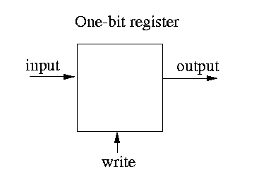
In contrast with combinational logic, the register only "latches" a new value when the clock signal rises. If the clock signal never goes high, the output will never change.
You can create "wider" registers or more bits by stacking a bunch of these together. CPU registers and SRAM/DRAM are essentially just a bunch of these stacked together.
These two pieces, combinational logic and registers (clocked state) are the only primitives you need to design digital logic.
A CPU itself is essentially a set of registers, along with combinational logic that determines how those registers update each clock cycle. The CPU has combinational logic that reads the binary encoding of the current instruction, which computes control signals that select which bits of combinational logic are active in order to update the registers properly for that instruction.1
For example, an instruction that adds $5$ to register A and stores the result in register B needs to route the encoding of $5$ in the instruction encoding and the contents of register A to an adder, and route the result to the input port of register B. Once the combinational logic has stabilized, when the clock signal goes high again, register B will successfully latch in the proper sum.
Just like software, there are compilers
As you might imagine, wiring up all of the bajillion required logic gates for your circuit by hand gets unwieldy pretty fast. So just like with programming, hardware designers increased the level of abstraction and started representing their circuit designs in something called a hardware description language (HDL).
HDLs let people write components by defining registers and hooking them up with primitives that correspond to combinational logic2. Here is a snippet of the HDL Verilog, which defines a "module" that holds a 4-bit register that is incremented by one with each clock cycle:
module counter(input wire clk, output reg [3:0] out);
    always @(posedge clk)
        out <= out + 1;
endmodule
We can read this as saying, "on the positive (rising) edge of the clk signal, we want to update the value of the out register with the contents of out plus $1$".
You can hand this off to one of the many Verilog compilers (hardware people call them "synthesizers") and they'll provide you with a "netlist", a list of all the low-level logic gates and the wires between them. In this case, the compiler knows to lower this circuit to a register whose input is combinational logic adding $1$ to its output.
The language scene is a little sad
Unfortunately, Verilog (and the expanded SystemVerilog) are some of the only HDLs widely in industrial use, despite Verilog's creation dating to back in the 80s. It seems like mostly everyone acknowledges that Verilog is a pretty shitty language. To give an idea: it silently allows many things that are almost always bugs and the "reg" construct can be synthesized to either a register or a normal wire, depending on context and use.
As I understand it, Verilog/SystemVerilog are dominant in industry despite sucking due to vendor lock-in with the big corporations that make synthesizers, simulators, and formal tools that only accept Verilog, as well as the industry's general aversion to doing risky things like try out new tools.
It's interesting that the language scene for software played out so differently: there has been an ever-increasing amount of language innovation, especially with projects like LLVM and now MLIR that provide narrow waists.
Hardware bugs == bad
A big difference from programming is that while a bug in google's search engine code is bad, a bug in an Intel chip is REALLY REALLY BAD. The result of this is that a very solid chunk (50% or more maybe?) of the chip-design process consists of verifying that your chip does what you want. To gain confidence your hardware code is groovy, companies use a mix of handwritten assembly tests, randomized testing, and running large applications (like Linux) on the CPU. These days, pretty much all testing actually occurs in simulation–either in software or on an FPGA.
One big difference from software is that hardware people actually use formal verification to prove correctness (at least for parts of their designs). It seems like a type of formal called "model checking" is what's most used, where an SMT solver does its best to prove that it is impossible for asserts in your hardware code to ever be false. While it's cool that hardware people actually use formal, it doesn't seem like it works all that well. I'm pretty curious to see if people begin to utilize theorem provers such as Lean more heavily now that LLMs provide cheap labor for writing the verbose proofs.
Resources
Just like with programming, there are tons of great videos on YouTube for learning about hardware. Here are some I'd especially recommend:
- Ben Eater has a famous series where he builds out an 8-bit CPU from low-level logic gates on a breadboard. He also has another series where he builds a computer around a 6502 CPU IC that is also great and touches on how the CPU interacts with other pieces of hardware.
- There are a ton of very clever tricks that modern CPUs employ to be really fast. If you want to understand what CPU buzzwords such as pipelining, Tomasulo's Algorithm, out-of-order execution, and branch prediction mean, then I'd recommend watching lecture recordings from a course on computer architecture, such as this one from ETH Zürich.
Modern CPUs have a lot of clever tricks to make them really fast which make this picture not quite right. But it's still a pretty good mental model to start with.
HDLs represent what's called the "Register Transfer Level" (RTL), which is to say they represent registers and the combinational logic that describes the transfer function over register values.